| 10 May 2021 |
 TheArduinoGuy TheArduinoGuy | The cones transfer the hit from the nesh head down onto the piezo | 12:11:19 |
| TheArduinoGuy | * The cones transfer the hit from the mesh head down onto the piezo | 12:11:25 |
| TheArduinoGuy | e.g...... https://youtu.be/MGMdCxhzjEg | 12:12:57 |
| TheArduinoGuy | It's high density foam so hard enough to transfer the shock of the hit but soft enough to not damage the mesh head | 12:26:21 |
 ionised ionised | That makes sense now that I've seen the video. The electronics that processes the piezo inputs might be interesting. Both piezos will output a signal when the drum is struck, I presume it prioritises based on signal magnitude. | 12:53:24 |
| TheArduinoGuy | Well in theory with the foam isolation there should only be tiny signals on the other piezo. | 12:54:42 |
| TheArduinoGuy | We shall see ! | 12:54:44 |
| TheArduinoGuy | and with a rimshot you want to get signals from both piezos | 12:55:05 |
| TheArduinoGuy | This is the Teensy playing drums over MIDI from yesterdays Medway Makers .... https://www.youtube.com/watch?v=oDDm7dNO8w4 | 13:14:04 |
| TheArduinoGuy | Ordered some op-amps to make a Signal Conditioner circuit for the piezos | 13:29:30 |
| ionised | The piezos give large output voltages so should be easy to detect. If you want to go for perfection piezo outputs are best processed with an op-amp configured as a charge amplifier. Only really useful if the signal is small in amplitude, has the advantage of good noise immunity. | 13:37:51 |
| TheArduinoGuy | I'm going to build this circuit.... | 13:41:07 |
| TheArduinoGuy | https://www.youtube.com/watch?v=y2Lmbts9IIs | 13:41:15 |
| TheArduinoGuy | Mainly to condfition the bouncy signal and then i'll detect the peak in software | 13:44:07 |
| TheArduinoGuy | * Mainly to condition the bouncy signal and then i'll detect the peak in software | 13:44:15 |
| ionised | That's a nice simple and elegant circuit. I like it. | 14:19:58 |
| TheArduinoGuy | Yeah i've ordered a whol ebunch of the op-amps so I can make plenty of these circuits for each pad input. I will need about 24 inputs minimum. | 15:19:19 |
| TheArduinoGuy | (4 x toms dual zone - head/rim) + (Snare dual zone head/rim) + Kick + (4 cymbals triple zone - bow/edge/bell/choke) + Cowbell | 15:21:27 |
| TheArduinoGuy | I ordered 10 x LM324 op-amps and they have 4 i/o's each so that's good for 40 inputs/outputs | 15:24:11 |
| TheArduinoGuy | @room don't forget we have 5 rooms in total. I see a lot of you are not in the other chat rooms we use often such as 'Current Projects', 'Project Ideas' and '3D Printing' | 15:26:08 |
| TheArduinoGuy | 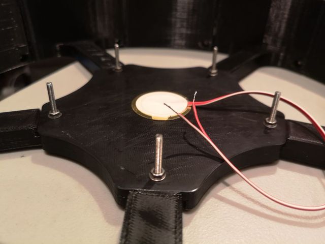
Download IMG_20210510_200213.jpg | 19:02:33 |
| TheArduinoGuy | 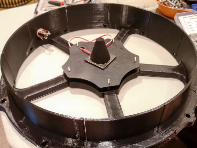
Download IMG_20210510_201709~2.jpg | 19:18:49 |
| TheArduinoGuy | 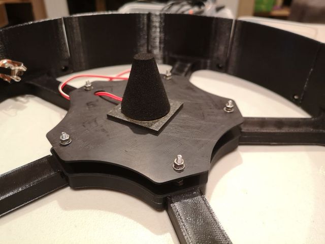
Download IMG_20210510_202639.jpg | 19:27:07 |
| 11 May 2021 |
| TheArduinoGuy | So I had issues last night. The rim was activcating when hitting the head. I thought I had the sensors wires up the wrong way around to begin with so swapped them but it was not that. | 08:51:34 |
| TheArduinoGuy | So I removed the bolt spacers and used 3M foam pads instead... | 08:51:55 |
| TheArduinoGuy | 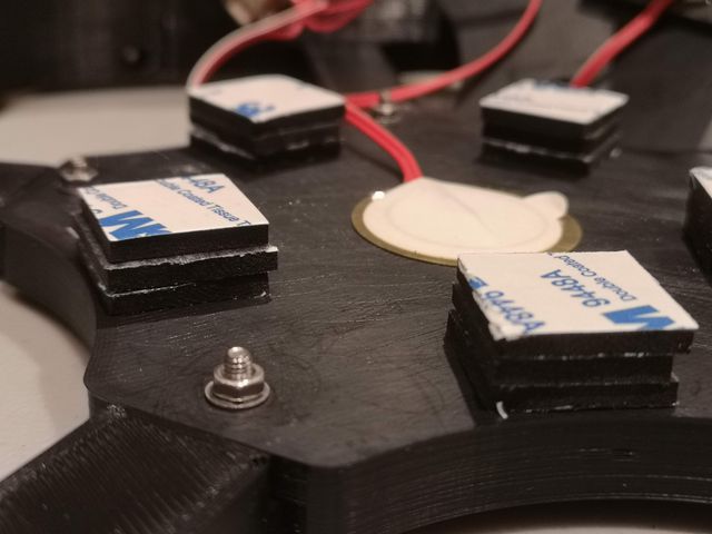
Download IMG_20210510_220435.jpg | 08:52:05 |
| TheArduinoGuy | But this did not solve the issue | 08:52:16 |
| TheArduinoGuy | So I took apart my existing pad and I noticed some resistors inline with both the positive and negative wires. 154K for ground and 124K and 68K for head and rim. | 08:53:00 |
| TheArduinoGuy | I also noticed the resitor on the positive side seems to gap across to ground as well. I have no idea why this might be... | 08:53:30 |
| TheArduinoGuy | 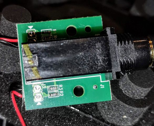
Download IMG_20210510_213327.jpg | 08:53:37 |
